Monday, December 15, 2008

Configuring SSL VPN on the ASA

Connections using the Cisco Anyconnect Client

The first thing to realize is that clientless SSL access is nothing more than a web page hosted by the ASA and using a self signed cert it's extremely easy to setup. What we are going to configure is much more involved...

Lets say you have a cable modem or DSL connection and you want to extend SSL VPN access to the outside world (at least those that have a valid account) you can do this by configuring your outside interface to accept connections (as well as DTLS - Datagram Transport Layer Security).


The next step is to define an address pool for this group of people coming in. In this case we have chosen a subset of the already established 192.168.168.0/24 network that is considered "inside". We have selected 192.168.168.220/30 - 192.168.168.221 and 192.168.168.222 since we only have the two free SSL licenses that came with the ASA....

Under the Configuration/ Remote Access VPN is a section labeled Network (Client) Access. Inside that you will see the address pool section. Simply create a pool and name it.


Now click on assignment policy and ensure that you have "use internal address pools" selected.


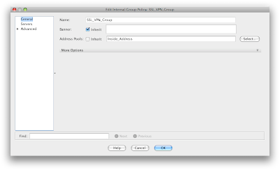
OK now we have access allowed in and a pool of addresses to give out. Lets create a group policy for these users under the Network (Client) Access. Add one called SSL_VPN_Group (if it's not already in place). Under the address pool section uncheck the inherit and select the pool we created.


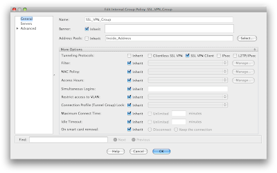
Under the more options section you will need to select the SSL Client option to ensure that you are accepting connections under this policy for AnyConnect users


under the servers options you can define your own internal DNS and WINS servers (WINS... haaa). In any case an internal DNS server is useful when users connect and want to resolve internal resources.

Under the more options in this section is the domain attribute that you can pass to the clients connecting. Again, a good thing to configure.

If you want to accept traffic that is destined to just your network then in the advanced section of the policy uncheck the inherit on split tunnel policy and choose "Tunnel Network List Below". Same goes for the Network List selection - uncheck this and define the list of networks that you want to accept traffic for.

**** Tons and tons of configuration options in the policy. For now we are going to leave everything as is and take the inherit settings.


Now lets go back to AnyConnect connection profiles and select one. In this case I have used the Default RA Group and modified the settings. Make sure you remember to check the box to enable this.


Now click on edit and lets get that address pool we created and the group policy we worked so hard on connected to this profile -
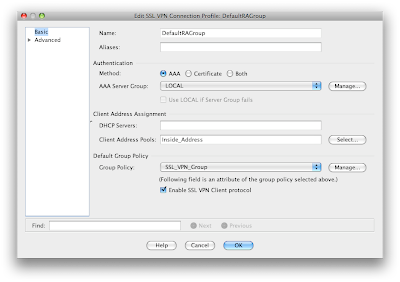


Under the advanced section in client addressing ensure that you have selected the "Use Address Pool" ** This really makes little sense since we already stated in the Address Assignment Policy how we wanted to hand out addresses. Man - 10,000 options.

Also under advanced settings you can select the interface that is doing the authentication - in this case the outside interface and the local database (or a radius server).


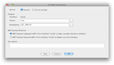
OK.... wow that was a lot. Lets connect and get going, right? Nope. You can connect, pass the authorization get a policy and an IP assigned (even DNS and domain) but you can't route anywhere... You need to exempt the traffic from NAT. This is done under the firewall NAT rules and states that traffic sourced from anywhere destined for the SSL_VPN /30 address range is exempt.


Here are the details of the NAT policy.


That should be it. Happy connecting.

Thursday, December 11, 2008

Cisco ASA Generic Access

ASA Access Rules

In order to allow generic access (web and ssh) from the outside to your internal network or DMZ you need to do one, possibly two things:

• Configure a policy to permit from a source address or range on a specific port to the network or more preferably a specific host.

• If your outside interface has a DHCP given address, then you will need to build a static NAT rule.

- Lets look at an example

1. We know that we want to allow http and ssh access from the address block 128.107.0.0 through 128.107.255.255 so we will create a network object with that /16 network and define it as "Cisco Registered"

2. We then create an access rule on the outside interface that states from that network object to "any" destination on port 80 (repeated for port 21) we want to permit it.

2a. You can optionally configure a time range for this acl to operate in. Example is 8 to 5 Monday through Friday http requests are allowed....


3. Now that you have the access permitted from a specific network into "any" device you need to pick the internal host (all having non routable IP's) and NAT the communication back out.

4. We want to have the http requests come to the web server at 192.168.1.10 so we configure a static NAT rule that says from the inside interface the source is (web server should be defined as a network object and assigned the IP 192.168.1.10) and that is translated to the outside interface using the interface IP (because we have a DHCP given IP and one exit point).

5. In the NAT rule you will want to enable PAT for the original port - 80 translated to port 80.

Wednesday, April 16, 2008

class-maps and policy-maps

The basic idea is this:

• create an L7 class-map with an action and a name
- define some match criteria

• create a policy-map with an action and a name
- refer back to a class-map
- action (like deny)

• create an L4 class-map with an action and a name
- match on a port number

• create another policy-map with an action and a name
- call out the L4 class-map
- call out the first policy map (the one that had the L7 class map in it)

• Apply the last policy-map - the one that summarized all of the class-maps and policy-maps together - to an interface

________________

• Create a class-map called "FTP_INSPECT_L7CLASS" that states we are inspecting traffic and it can match on any of the items defined:
class-map type ftp inspect match-any FTP_INSPECT_L7CLASS
!

• This is the match criteria (and the only one listed) that says look for someone making a directory:
match request-method mkdir
!

________________

• Now the policy-map - this will inspect ftp traffic and do a first match
policy-map type inspect ftp first-match FTP_INSPECT_L7POLICY
!

! This statement in the policy-map refers to the class-map we already created called FTP_INSPECT_L7CLASS which was looking for anyone making a directory
class FTP_INSPECT_L7CLASS
!

! Now the action - deny it
deny
!

________________


• OK, another class-map, this time L4
class-map match-all FTP_INSPECT_L4CLASS
!

• Hey look a description!
description FTP command inspection of incoming traffic
!

• Lets match on FTP port 21 (the port that commands are issued on)
match port tcp eq 21

________________

• Now the policy-map setup as a multimatch
policy-map multi-match FTP_INSPECT_L4POLICY
!

• The class, in this case its referring to the class-map we made called FTP_INSPECT_L4CLASS
class FTP_INSPECT_L4CLASS
!

• OK now the confusing part - this action under the class FTP_INSPECT_L4CLASS says inspect ftp traffic strictly adhering to the policy-map
FTP_INSPECT_L7POLICY that itself has a class-map called FTP_INSPECT_L7CLASS that said look for anyone making a directory and then an action to deny it.....

inspect ftp strict policy FTP_INSPECT_L7POLICY
!

________________

• Here is where the rubber meats the road and the service-policy is applied to the interface

interface vlan 50
!
ip address 172.16.1.100 255.255.255.0
!
service-policy input FTP_INSPECT_L4POLICY
!

Thursday, February 14, 2008

Cisco bandwidth statement

IGRP, EIGRP, and OSPF all use the bandwidth statement.
TCP will also adjust its initial retransmission parameters based on the bandwidth configured on the interface.

OSPF uses cost as its routing metric, which it calculates using bandwidth.

OSPF takes 108 and divides it by the bandwidth of the interface. To calculate the cost of a full T1, OSPF divides 100,000,000 by 1,544,000, which returns an OSPF cost of 64.
(Cisco routers don't use floating-point math, so they drop the numbers after the decimal.)

On the other hand, EIGRP uses the bandwidth of the link to calculate its routing metric.
EIGRP metric formula:

metric = [K1*bandwidth + (K2*bandwidth)/(256 - load)
+ K3*delay] * [K5/(reliability + K4)]

Example:

interface Serial0/0
bandwidth 128
ip address X.X.X.X 255.255.255.0

This command has only one option—the bandwidth, in kilobits, of the interface.

Router(config-if)# bandwidth ?
<1-10000000> Bandwidth in kilobits
Router(config-if)#bandwidth

There are always default bandwidth values set for each type of interface, such as the Serial
interface:

Router# show interface s0/0
Serial0/0 is administratively down, line protocol is down
Hardware is PowerQUICC Serial
MTU 1500 bytes, BW 1544 Kbit, DLY 20000 usec,

In the case of a serial interface, the default bandwidth is 1,544 K (or a full T1 circuit).
However, you could have a fractional T1 circuit, and the default may be incorrect.

Wednesday, February 6, 2008

IPSec Configurations

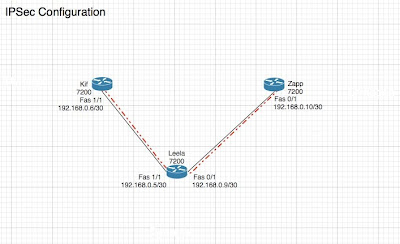
This is a simple IPSec configuration done between two 7200 routers Kif (192.168.0.6/30) and Zapp (192.168.0.10/30), both going through a third 7200 Leela (192.168.0.5/30 and 192.168.0.9/30 respectively). You need to have connectivity from Kif to Zapp before this starts so go ahead and pick your favorite routing protocol and add something like this to all three:
!
router ospf 1
log-adjacency-changes
redistribute connected subnets
network 192.168.0.0 0.0.0.255 area 0


The diagram is here:


** One thing to note in this, anything that I have defined in the config I have put in upper case lettering. It should be easy to spot things that you need to input as opposed to what is part of the default commands.

• We're going to start with the configuration from Kif and then show you at the end the commands that will be different on Zapp. The first thing we want to do is define the Internet Key Exchange (IKE) Policy. Here we are using Internet Security Association and Key Management Protocol (ISAKAMP) for IKE phase 1 negotiation:
!
crypto isakmp policy 1


- The next part of this configuration specifies the hash and authentication method:
!
hash md5
authentication pre-share


- Now we set the pre shared key and our peer address:
!
crypto isakmp key CISCO address 192.168.0.10


• Now we move onto the transform set which is a mix of security protocols and algorithms:
!
crypto ipsec transform-set DES1 esp-des esp-md5-hmac

- As you can see I put in the "DES1" statement. Thats the name we are using for this transform set. We will see it again later in the configuration.


• Moving onto the crypto map:
!
crypto map DES1_MAP 1 ipsec-isakmp


- Now we set the peer address (same one that we put in the key command above):
!
set peer 192.168.0.10


- Now here is the transform set we defined earlier:
!
set transform-set DES1


- And finally the always confusing match statement. This says anything that matches the ACL we defined (in this case 115) needs to pass through this convoluted configuration we have constructed:
!
match address 115


- Here is ACL 115 so you can see what we have said needs to pass through this:
!
access-list 115 permit ip host 192.168.0.6 host 192.168.0.10

____________________________________________

• Now here are the differences in the config for Zapp:
!
- Crypto address needs to point to the peer
crypto isakmp key cisco address 192.168.0.6 -> this is the IP of Kif's Fastethernet 1/1


- Under crypto map DES1_MAP 1 ipsec-isakmp
set peer 192.168.0.6 -> we know what this is...
!

- ACL needs to be reversed
access-list 115 permit ip host 192.168.0.10 host 192.168.0.6

And thats it! A huge amount of typing and head scratching to make something so simple work. Lets hope we can put this in the time capsule and open it in five years and laugh...